Closing this gap is crucial, and it can be achieved through companies and engineers adopting a Design for Manufacturability (DFM) strategy. DFM enables designers to incorporate key manufacturability factors into sheet-metal designs, minimizing errors, engineering change orders (ECOs), and bridging the gap between ideal and real-world production. This strategy emphasizes simplifying designs, reducing part counts, standardizing components for versatile applications, and offering insights for easier manufacturing processes.
What we cover in this blog?
Key Takeaways
- Prioritize material selection and geometric considerations for efficient sheet metal fabrication.
- Embrace DFM principles to minimize costs and enhance product quality in manufacturing.
- Implement design guidelines and tolerance specifications tailored for sheet metal production.
- Optimize assembly techniques to streamline fabrication processes and improve overall efficiency.
Design For Manufacturability (DFM) Guidelines
Design for manufacturability (DFM) is a proactive engineering strategy that accounts for the limitations of current manufacturing capabilities. By considering the specific tools and materials available, the DFM process enables engineers to create computer-aided design systems that are tailor-made for the chosen manufacturing process.
DFM can minimize production costs, reduce lead times, and enhance overall product performance. Ultimately, DFM is a valuable approach that can help to ensure that products are not only well-designed but also practical and cost-effective to produce.
Therefore, when manufacturing, it’s important to follow specific guidelines to ensure a successful process and outcome. These guidelines are part of the design for manufacturability and include the following:
Minimize part count
Part count reduction helps reduce costs, simplifies assembly and production, and increases the strength of the part quality final product. Parts should be combined into larger components.
Make assembly easy
Designs should be easily completed using the chosen manufacturing tooling process. For example, in sheet metal design and fabrication, this means ensuring the requested bends, cuts, and perforations are easily performed with standard tools.
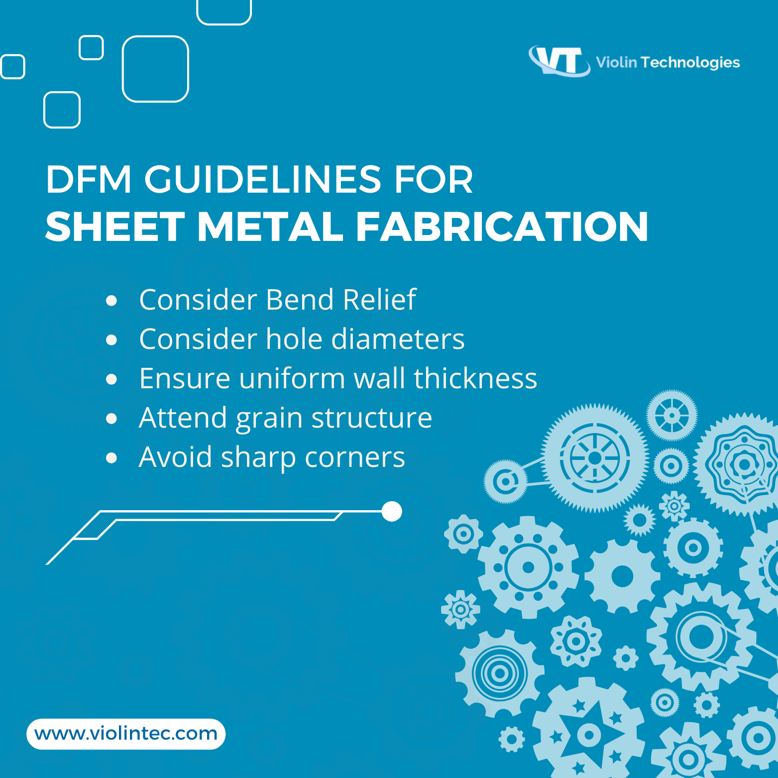
Consider bend relief
When transitioning from a bend to a flat surface or another bend, sheet metal may tear depending on the boundary geometry. It’s common practice to provide relief to the flange for easier bending. Before determining the bend radius and flange length, consider the material thickness and required tooling accuracy.
Typically, the bend radius should be equal to or greater than the sheet metal thickness. Flange length is usually four times the material thickness. For air-bending dies shaped like a ‘V,’ the material must match the width of the V, and the flange should equal half the V opening. In essence, thicker material necessitates a wider die, which requires a longer flange.

Consider hole diameter and locations
Holes are frequently incorporated into sheet metal components. Small holes are typically either punched or laser-cut, depending on the available equipment. It’s generally recommended that the diameter of punched holes be equal to the sheet thickness. If the hole diameter is too small, there’s a higher risk of the punch breaking or bending during operation.
Holes should be large enough to avoid burrs or burnish. They should be located at least two thicknesses apart from each item, and each item should be one thickness away from the edge. If a hole is near a full bend radius, then it should be 1.5 thickness away from the bend radius.
With the assistance of an expert contract manufacturer, you can ensure ECOs are a few and the product is brought to market faster.
Ensure Uniform Wall Thickness
Choosing the right sheet thickness is crucial in sheet metal fabrication. It impacts factors like part strength, weight, and design features such as bend radii, hole sizes, and flange length. Maintaining consistent thickness across parts is vital for consistent quality and performance.
Attend grain structure
The grain structure of metal sheets is crucial for preventing cracks in sheet-metal parts with lugs or tabs cut on three sides and bent inward or outward, where other components are often attached. Engineers modeling such parts must grasp the grain structure of the metal coil to be used.
Lugs formed parallel to the grain direction tend to develop cracks. While exceptions may arise in complex designs, the recommended practice is to form lugs perpendicular or at an angle less than 45 degrees to the grain direction. While there are exceptions, talking to the sheet metal fabricator helps ensure a better outcome.
Avoid Sharp corners and unnecessary points
Avoid sharp corners and unnecessary points or areas that are susceptible to breakage under pressure. Aesthetically pleasing rounded corners would be a preferable option.
By following these guidelines, custom metal stamping manufacturers in India produce high-quality products that are cost-effective, easy to assemble, and strong enough to withstand the pressures of everyday use.
Conclusion
To ensure successful manufacturing of a part, engineers should adhere to the DFM specifications when creating the sheet metal design. The DFM analysis enables engineers to receive an instant quote for their preferred manufacturing method. By utilizing this DFM analysis, engineers can make the necessary modifications to ensure a smooth and efficient manufacturing process.
Frequently Asked Questions
What are the five factors for design for manufacturability?
1. Processes: Choose an appropriate manufacturing process. CAD designers are important.
2. Material Selection: Choose the right material based on the product’s end-use, cost, and manufacturing process.
3. Design for Assembly: Optimize design for easy assembly time.
4. Design for Manufacturing: Optimize design for efficient manufacturing.
5. Testing and Quality Control: Test the product and implement quality control.
What are the basic DFM rules for sheet thickness (T) in sheet metal design?
For optimal placement and spacing, it is recommended to place a hole at a distance of 1.5T to 2T from the edge if it is located near the edge. Similarly, the distance between holes and bends should be able to accommodate the bend area (H) and be situated close to the bend to ensure a strong and reliable structure.
What are the considerations for design for manufacturability?
Choosing the right manufacturing method is crucial to creating successful products. Several factors, such as price, production materials, volume, surface finish, production needs, and punch-to-die clearance, are evaluated to select the most suitable process for a particular product.
How can engineers ensure the successful implementation of DFM in sheet metal fabrication?
Effective communication between engineers and fabricators is essential to ensure that design considerations align with manufacturing capabilities and requirements, leading to optimal outcomes and high-quality products.

Aparna Sushumna
About the Author
Aparna Sushumna, a mother to a hyperactive toddler who is all over the house. I aspire to be a decent content developer. A Bachelorette of technology says my qualification but I anticipated being a singer. Thanks to the recession, I dwelled into various jobs, from coding to being a tech support executive to a help desk professional, only to conclude that there is something else I wish to do. Here I am to accomplish my profound passion for content writing. Music, nature, jewelry, beauty, mythology, life quotes, celebs, and their life, being my areas of interest.

